Smart Eye [01]: Getting Started
Published:
The Smart Eye Pro system is a head and gaze tracking system, which measures the subject’s head pose and gaze direction in 3D. In addition, information about eye lid opening values and pupil dilation can be measured.
Setup Wizard
To start the tracking, the following tasks need to be performed:
- Assemble the system. Place the camera(s) in a fix and stable position to avoid movement during tracking. Make sure all cables are connected.
- Perform a “Camera Calibration” (F3).
- Define the “World Coordinate System (WCS)” (CTRL+D).
- Start “Tracking” by pressing or selecting “Tracking Start “ in the “Action” menu (F2).
- Perform a “Gaze Calibration” (CTRL+G).
- Verify that the system operates correctly by opening a “Values View” in the “Window” menu (SHIFT+V).
- Data can be sent to one or more client applications specified in the Settings->Logging… tab (ALT+F8).
- Save the automatically created profile by pressing Action->Tracking->Stop, followed by pressing Profile->Save.
Before Setting Up
Before Camera Caliberation, it is important to check the aperture and focus settings on the camera. Since the aperture has influence on the focus, it is recommended to first adjust the aperture and then the focus
Adjusting Aperture
The brightness is adjusted for one camera after the other. The subject should look towards the active camera so that its face is visible in the center.
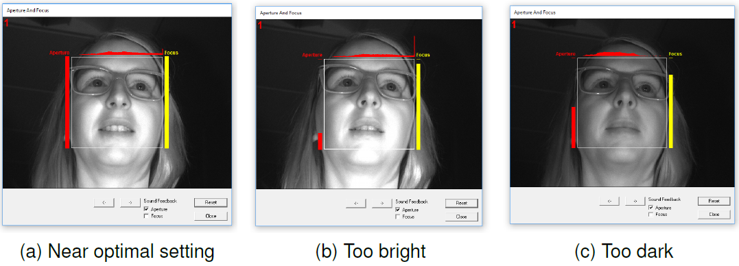
A gray value histogram is shown above the camera image. Ideally the gray value histogram includes the full spectrum from low (left) to high (right) gray values. The optimal aperture setting is reached when the red bar on the left side of the box reaches its maximum. It does not necessarily need to reach the top. The achievable maximum can be found by moving the aperture further until the bar decreases again and then back to the maximum.
Adjusting Focus
The focus is adjusted for one camera after the other. The subject should look towards the active camera so that its face is visible in the center.
the yellow bar on the right side the window indicates the quality of the focus setting. The optimal setting is reached when the yellow bar on the right side of the box reaches its maximum. It does not necessarily need to reach the top. The achievable maximum can be found by moving the focus further until the bar again and then back to the maximum.
Camera Caliberation
Once the cameras have been positioned and fixated in the desired positions a camera calibration is required for the software to learn the positions and orientations of the cameras.
- Choose System Setup->Calibrate…. This will bring up the camera calibration dialog, showing live video from the connected cameras.
- Hold the chessboard in front of the cameras to perform the calibration.
- Try to make the chessboard visible in as many cameras as possible at the same time.
- Tilt and move the chessboard around a lot in all directions until the progress bar for each camera is filled. When all bars are filled the application will automatically proceed to the “Verify Camera Calibration” dialog and display the calibration result.
It is advisable to always perform the camera calibration procedure before each test subject if the cameras are mounted in not perfectly stable positions or mounted in positions where there is a risk of someone accidentally touching them.
World Coordinate System
The World Coordinate System (WCS) defines the origin and orientation of the 3D-world, with respect to the camera(s). The WCS definition is required to start tracking and to define the reference coordinate system for the gaze and head model values.
Follow these steps to define the WCS automatically:
- Make sure the selected definition method is “automatic”.
- Select System Setup->Coordinate System Definition… or press the Define button in the tool bar.
- Select the cameras that shall be used by checking the respective box.
- Confirm by looking at the values under “Chessboard Characteristics” that the correct chessboard size is used.
- Place/Hold the chessboard steady in the position where the origin of the coordinate system shall be defined.
- When the chessboard is detected by the system, the coordinate system becomes visible and the OK button becomes active. Press it to define the WCS.
If the rotation and origin of the chessboard are used to define the WCS it is recommended to mount the chessboard on a fixture to make it easy to place the chessboard in the same position each time. It is necessary to redefine the WCS each time the camera(s) have been moved.
Tracking
Tracking is started by selecting Action->Start Tracking or clicking on the Track button in the Control Toolbar. Stop tracking via Action->Stop Tracking or click the Track button again.
A prerequisites to start tracking are that the cameras are calibrated and, if running in the “Use Profile” tracking mode, that a profile is loaded.
Gaze Caliberation
The gaze direction measurement is affected by several parameters such as the individual eye geometry, refracting eyeglasses, and individual characteristics such as strabismus. This means the gaze direction needs to be adjusted uniquely for each individual. The purpose of the gaze calibration is to determine the difference between the visual and the optical axis of the eye and other relevant eye parameters.
To perform a gaze calibration, follow the steps as described below:
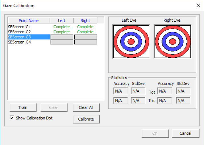
- Open the Gaze Calibration dialog by selecting “Profile->Gaze Calibration”.
- Select a calibration point from the list in the “Gaze Calibration” dialog.
- Make sure that the subject looks at the calibration point while the calibration data is collected.
- Press the Train button or SPACE to start the calibration on the selected object. The system will “train” on this object until Space is pressed again or until the progress bar is filled.
- Do this for the desired number of calibration points.
- If the subject has been looking somewhere else during “training”, the data collection needs to be redone. Press Clear or the Delete button to clear the selected sample and allow a new “training”.
- Go through all calibration objects and check that the blue dots are close together without any outliers. As long as the noise is small there is no harm if the blue dots have an offset from the target. If outliers exist, the current calibration point should be cleared and “trained” again.
- When calibration points look good, the gaze calibration can be saved in the automatically created profile.
Viewing
Smart eye provides several different ways to visualize the data:
- Images View
- Values View
- Graph Vew
- 2D/3D World View
- Zone View
- Screen View
Data Logging
Three methods are provided for data logging.
- Text Output
- TCP/UDP Communication
- CAN Communication
Stopping and Saving
After starting tracking, the profile is initialized automatically when the face is visible in at least one camera. During tracking the profile is updated and improved continuously, i.e. more tracking templates are added to cover a wider range of head rotations and the 3D head geometry is recalculated to better fit the subject’s head.
Turn off tracking and save the profile under Profile->Save as…. The profile name will appear in the top-left corner of the application window.
When a gaze calibration is performed, it can be saved to the profile, by turning off tracking and selecting Profile->Save.
Make sure to reload or regenerate the automatic profile when changing subjects.
Comments